Machine Room Layout Plan With Section Details And Rope Hole Sizes
Description
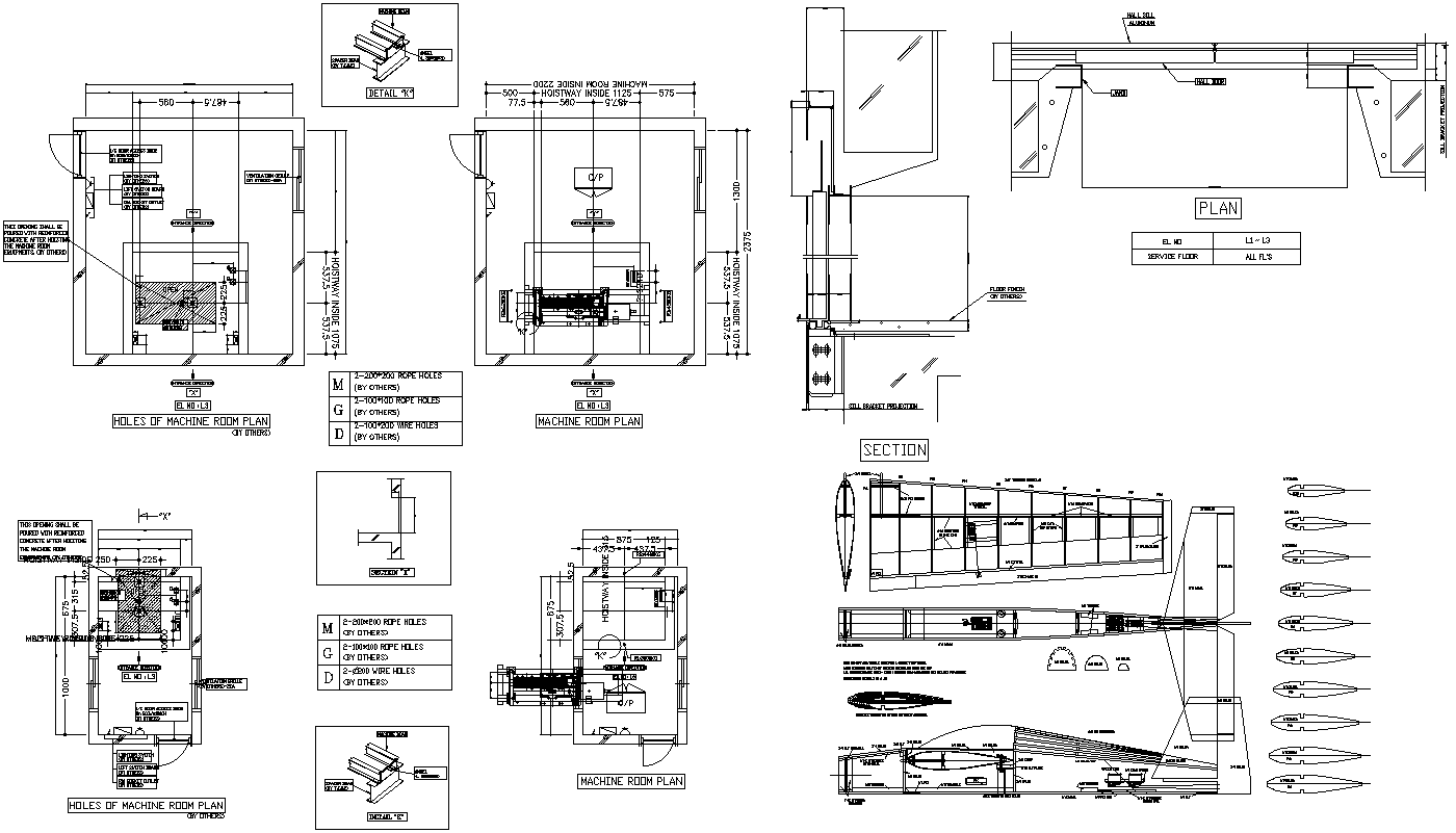
This AutoCAD DWG drawing presents a detailed machine room layout plan with coordinated plan and section views prepared for precise equipment installation and coordination. The drawing clearly shows the machine room plan with equipment positioning, foundation blocks, service floor levels, and access clearances. Dimensioned layouts indicate overall room widths of approximately 575 mm and 580 mm clearances, machine base alignment, and shaft interface locations. Rope hole layouts are accurately marked, including 200 mm diameter rope holes and grouped openings defined for mechanical routing. Wall thicknesses, floor offsets, and anchoring positions are clearly labeled to support construction accuracy and installation sequencing.
The sectional views provide detailed insight into vertical relationships, including floor-to-floor heights, slab thickness, beam support conditions, and machine mounting elevations. Additional details include bracket sections, opening reinforcement, and interface details between machine components and structural elements. The drawing also illustrates plan references for service floors, opening centers, and tolerance notes required for execution. This AutoCAD DWG file is suitable for architects, civil engineers, mechanical engineers, and consultants who require accurate machine room drawings with measurements, plan section coordination, and installation-ready details for industrial or building services projects.
File Type:
DWG
File Size:
647 KB
Category::
Electrical
Sub Category::
Architecture Electrical Plans
type:
Gold

Uploaded by:
Eiz
Luna